How To Use Voltage Parameters: A Practical Guide For Accurate Measurement And Configuration
Voltage parameters are fundamental settings and specifications that define the electrical potential difference in a system. Correctly understanding and applying these parameters is critical for the design, testing, and safe operation of any electronic device or circuit. This guide provides a comprehensive, step-by-step approach to effectively using voltage parameters, whether you are taking measurements with a multimeter or configuring a power supply.
Before diving into procedures, it's essential to grasp the key voltage parameters you will encounter:
1. Voltage Level: The nominal value, such as 5V DC or 230V AC. 2. Tolerance: The permissible deviation from the nominal level (e.g., 5V ±5%). 3. Ripple & Noise: Small, rapid, and unwanted AC fluctuations superimposed on a DC signal. 4. Accuracy: The degree to which a measured value conforms to its true value. 5. Input Impedance: The effective resistance of a measuring instrument (like a multimeter), which can affect the circuit being measured, especially high-impedance ones. 6. Overvoltage Category (CAT Rating): A safety rating for test equipment defining the type of electrical environment it can safely be used in (e.g., CAT III for distribution panels).
Step 1: Safety First Always begin by assessing the environment. Identify the voltage category (CAT rating) of your measurement point and ensure your multimeter and test leads are rated for a higher category (e.g., use a CAT III meter for a household outlet). Inspect the test leads for any cracks or exposed wire.
Step 2: Meter ConfigurationSelect the Correct Function: Turn the dial to "V" for voltage.Choose AC or DC: Select "V⎓" for Direct Current (e.g., batteries, PCBs) or "V~" for Alternating Current (e.g., wall outlets, transformers). Selecting the wrong type will give an incorrect reading.Set the Range (if using a manual-ranging meter): Start with the highest range and work down to prevent overloading the meter. For auto-ranging meters, the instrument will select the appropriate range automatically.
Step 3: Probing the CircuitConnect the Leads: Insert the black lead into the COM (common) jack and the red lead into the V/Ω jack.Apply the Probes: For DC measurements, connect the red probe to the positive point and the black probe to the negative or ground. For AC, polarity is not critical. Ensure a firm connection.
Step 4: Reading and InterpretationObserve the value on the display. Note the unit (mV, V).For DC measurements, a negative sign indicates reversed polarity.Understand the meter's accuracy specification. If your meter has a ±1% accuracy and reads 10.00V, the true voltage is between 9.90V and 10.10V.
Step 1: Initial SetupEnsure the power supply is off or the output is disabled.Connect your device to the output terminals, observing correct polarity.
Step 2: Setting Voltage and Current LimitsVoltage Setting: Use the voltage knob or keypad to set the desired output voltage level (e.g., 12.0V).Current Limiting (Crucial Step): Before enabling the output, turn the current knob all the way down. With the output disabled, short the positive and negative terminals with a wire. Slowly increase the current limit until the display shows the maximum current you want to allow (e.g., 1.0A). This protects your device from excessive current in case of a fault. Remove the short.
Step 3: Enabling Output and VerifyingTurn on the output. The voltage display should show your set parameter.Use a multimeter to independently verify the actual output voltage of the power supply at the device's terminals to account for any voltage drop in the cables.
Step 4: Monitoring for StabilityObserve the voltage reading on the power supply and/or your multimeter once the load (your device) is connected. Check for any significant droop or ripple that falls outside your required parameters.
1. Minimizing Noise in Measurements: For sensitive low-voltage circuits, use shielded cables and keep test leads away from sources of AC magnetic fields like power transformers. Use the "Relative" (REL) or "Null" function on your multimeter to zero out the inherent offset of your test leads. 2. Measuring Ripple: To accurately measure ripple on a DC power rail, switch your multimeter to AC Voltage mode. However, for better accuracy, use an oscilloscope. A common trick is to use a "spring tip" adapter on the probe to minimize the loop area and pick up less environmental noise. 3. Handling Floating Measurements: When measuring a voltage that is not referenced to earth ground (a floating circuit), be aware that the multimeter's ground reference might create an unintended short circuit. In such cases, use differential probes or two channels on an oscilloscope in math mode (Channel 1 - Channel 2). 4. Using Data Logging: For monitoring voltage parameters over time (e.g., battery discharge), use a multimeter with data logging capabilities or one that can interface with a PC. This allows you to track stability, transients, and long-term drift.
Never Exceed the Voltage and Category Rating: This is the most important rule. Using a CAT I meter on a mains power line is extremely dangerous and can lead to explosion and fire.Beware of Ghost Voltages: In high-impedance circuits, capacitive coupling can induce small "ghost" voltages that a modern digital multimeter with high input impedance may register. Use a low-impedance (LoZ) mode if your meter has it to dissipate this phantom voltage and get a true reading.Understand Ground Loops: When connecting multiple grounded instruments (e.g., a power supply and an oscilloscope), you can create ground loops that introduce hum into your measurements or even damage equipment. Use isolated measurement tools or be mindful of connection points.Calibration is Key: The accuracy of your voltage parameters is only as good as your instrument's calibration. Regularly service and calibrate your multimeters and power supplies according to the manufacturer's schedule, especially if used for critical applications.Parasitic Effects: In high-frequency circuits, the long leads of a multimeter can act as antennas, affecting the circuit's behavior and giving inaccurate readings. In these scenarios, an oscilloscope with a properly compensated probe is the correct tool.By systematically following these steps, tips, and precautions, you can confidently and safely measure, set, and verify voltage parameters. Mastering these fundamentals is the first step toward ensuring the reliability, performance, and safety of all your electronic projects and systems.
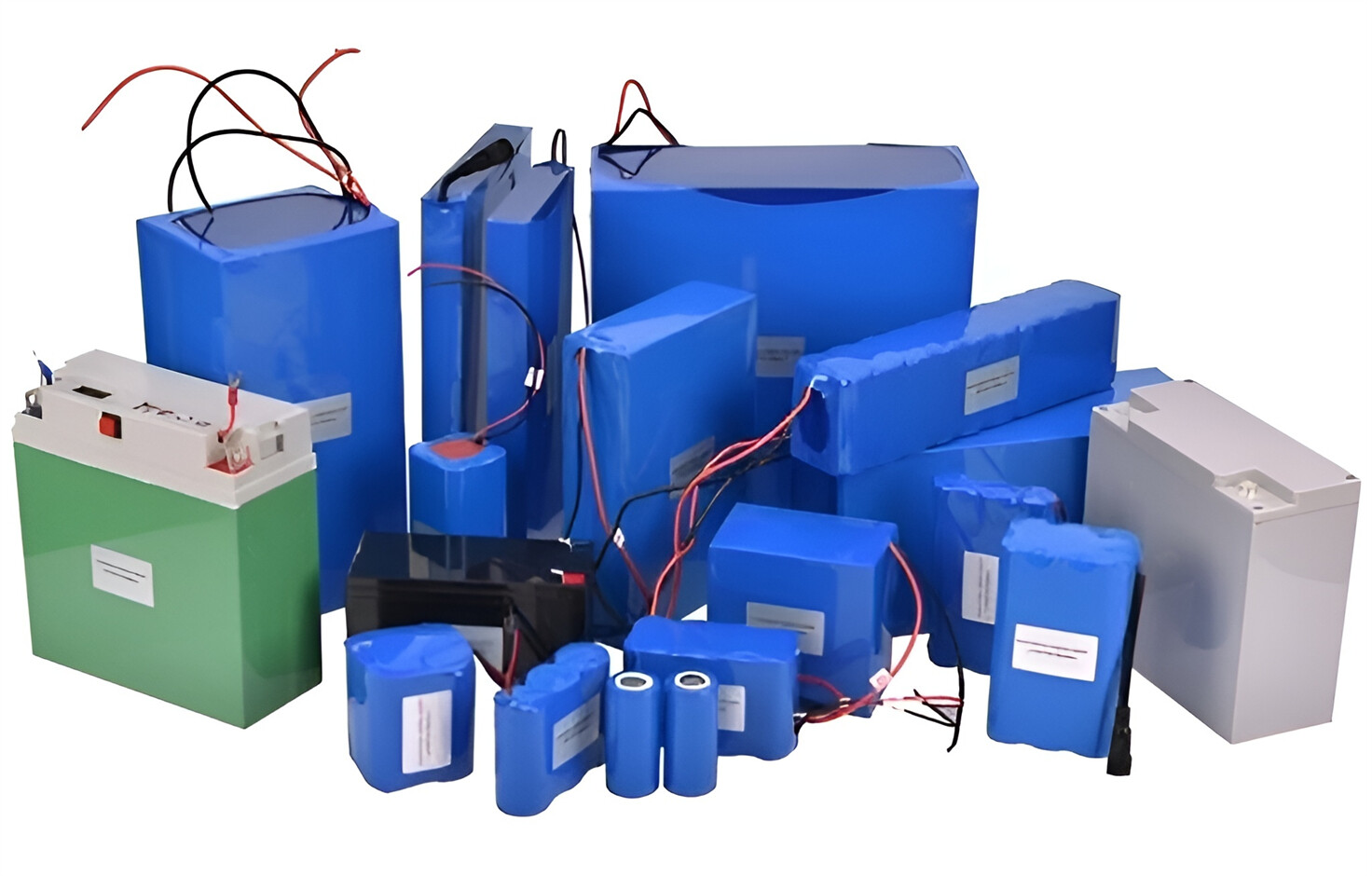
Customized/OEM/ODM Service
HomSolar Supports Lifepo4 battery pack customization/OEM/ODM service, welcome to contact us and tell us your needs.


HomSolar: Your One-stop LiFePO4 Battery Pack & ESS Solution Manufacturer
Our line of LiFePO4 (LFP) batteries offer a solution to demanding applications that require a lighter weight, longer life, and higher capacity battery. Features include advanced battery management systems (BMS), Bluetooth® communication and active intelligent monitoring.
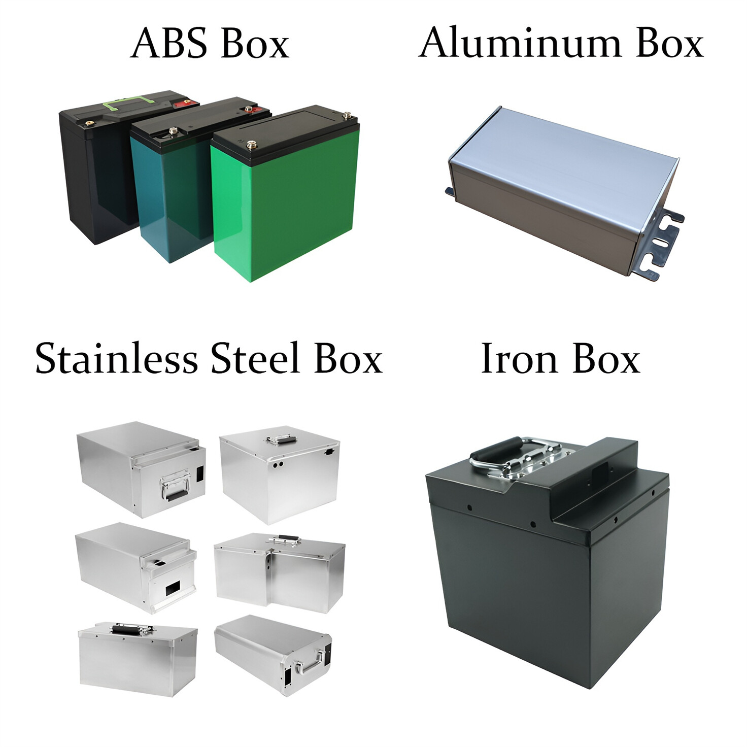
Customised Lithium Iron Phosphate Battery Casing
ABS plastic housing, aluminium housing, stainless steel housing and iron housing are available, and can also be designed and customised according to your needs.
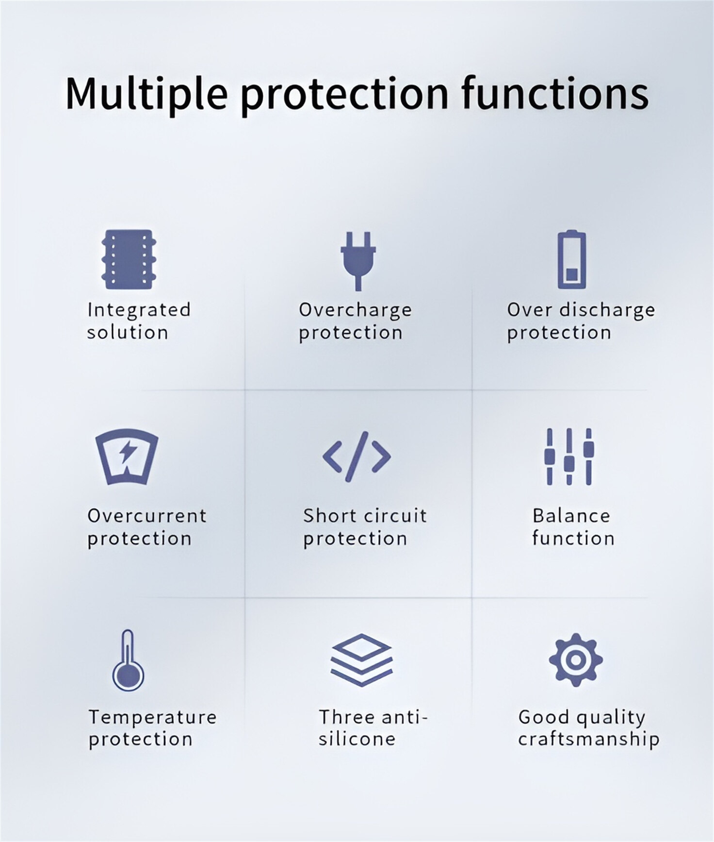
HomSolar Smart BMS
Intelligent Battery Management System for HomSolar Energy Storage System. Bluetooth, temperature sensor, LCD display, CAN interface, UART interface also available.

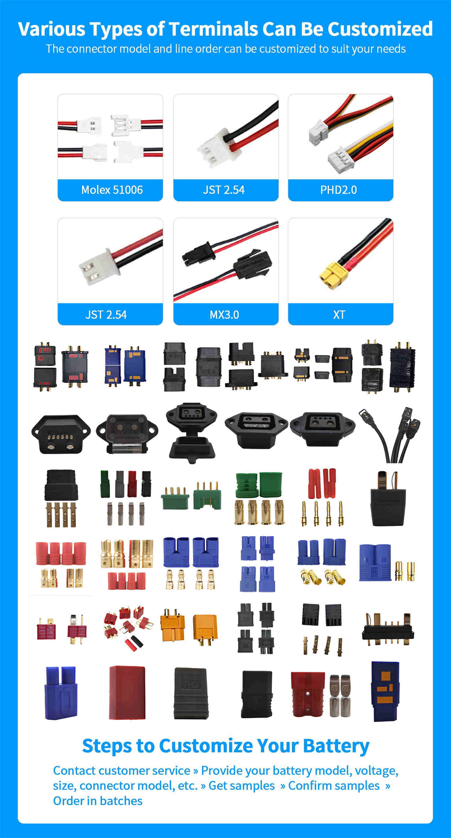
Terminals & Plugs Can Be Customized
A wide range of terminals and plugs can be customised to suit the application needs of your battery products.
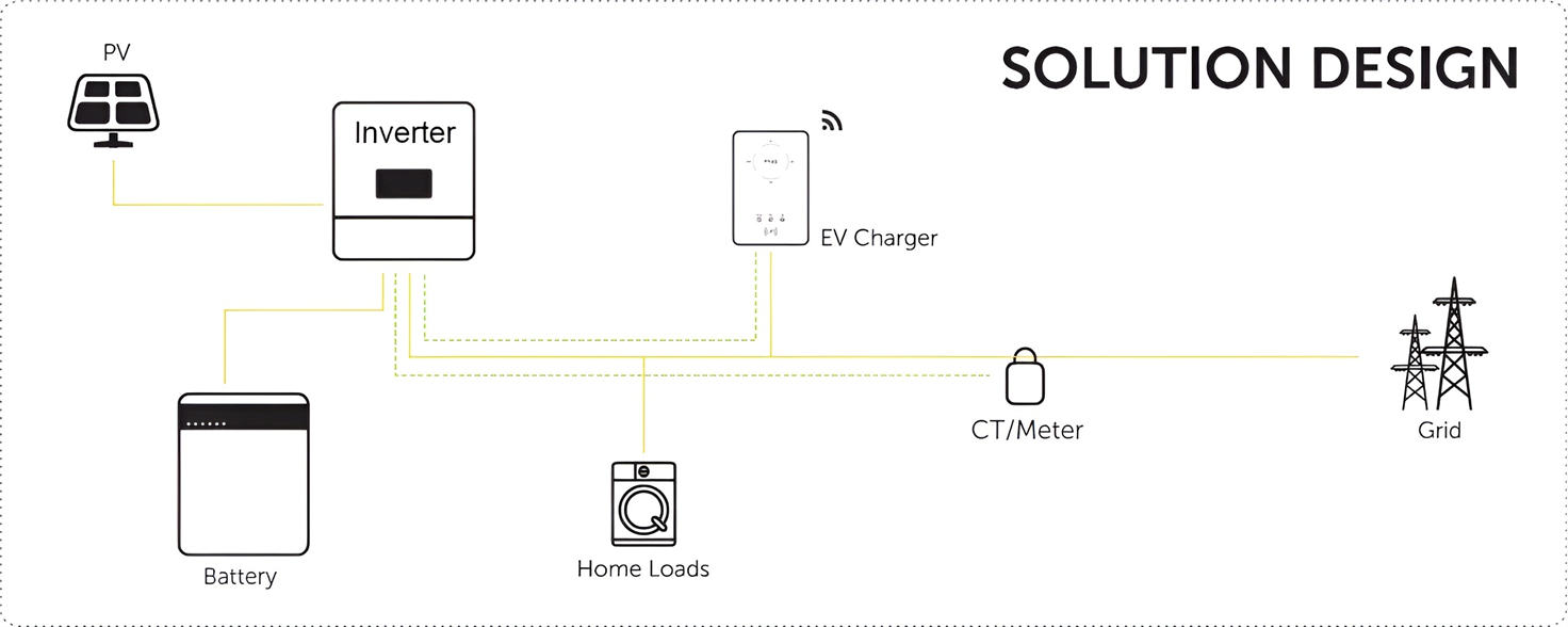
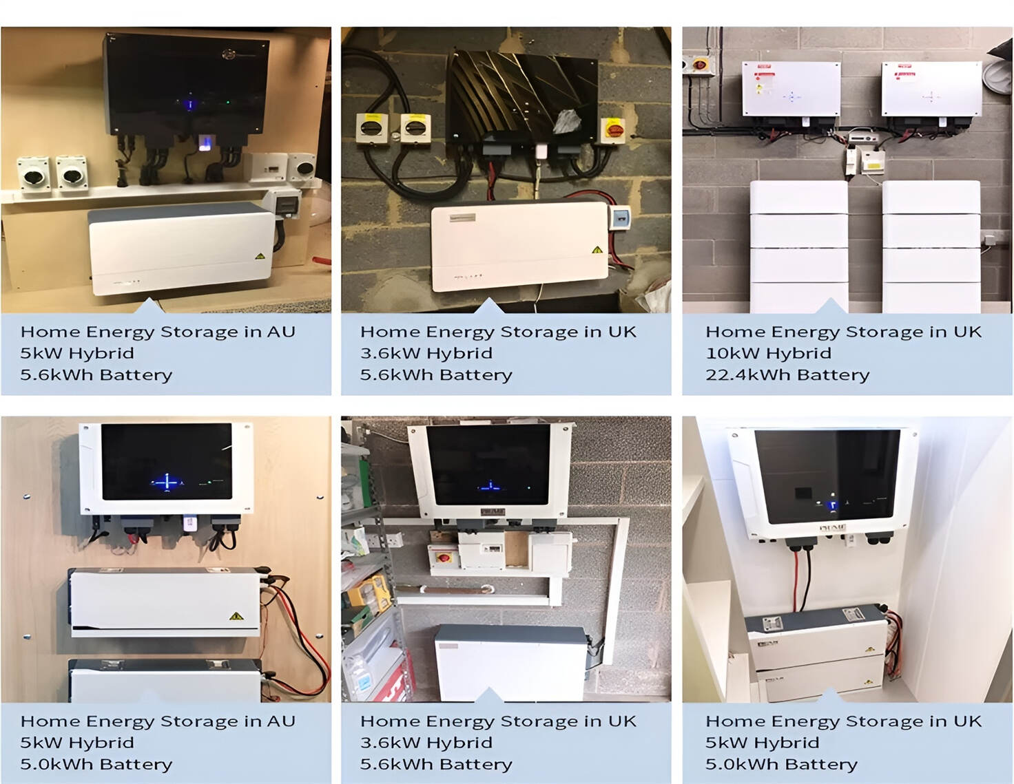
Well-designed Solutions for Energy Storage Systems
We will design the perfect energy storage system solution according to your needs, so that you can easily solve the specific industry applications of battery products.


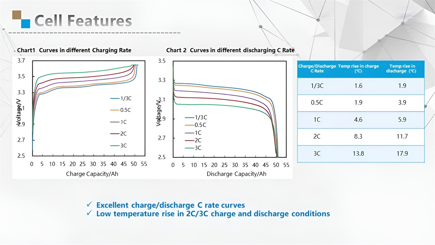
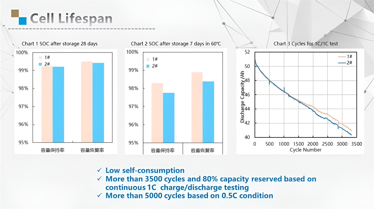
About Our Battery Cells
Our energy storage system products use brand new grade A LiFePO4 cells with a battery lifespan of more than 4,000 charge/discharge cycles.

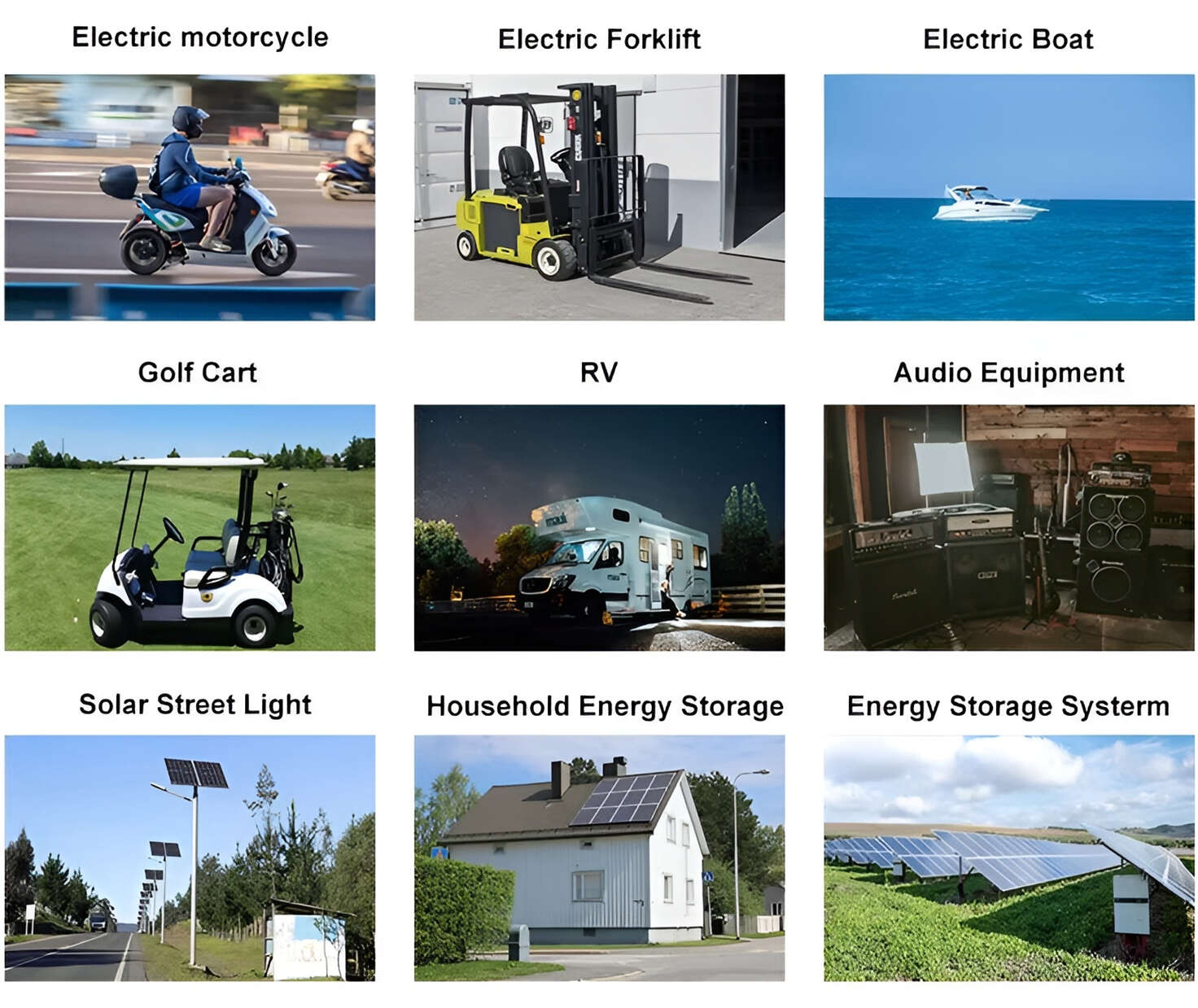
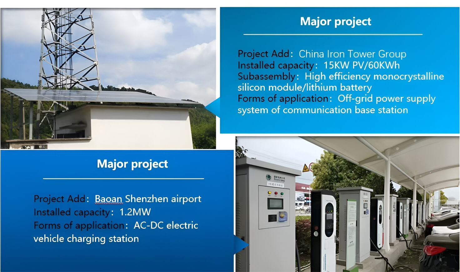
Applications in Different Industries
We supply customized & OEM battery pack, assemble cells with wiring, fuse and plastic cover, all the cell wires connected to PCB plug or built BMS.
Applications: E-bike, Electric Scooter, Golf Carts, RV, Electric Wheelchair, Electric Tools, Robot Cleaner, Robot Sweeper, Solar Energy Storage System, Emergency Light, Solar Power Light, Medical Equipment, UPS Backup Power Supply.
We can provide you with customized services. We have the ability to provide a vertical supply chain, from single cells to pack/module and to a complete power solution with BMS, etc.

HomSolar (Shenzhen) Technology Co., Ltd


")

